Leave Your Message

What Is a Sany Skid Steer and How Does It Work?

A Sany Skid Steer is a compact loader built for tight spaces, quick attachment changes, and demanding site work. Its short frame can turn within its own working area. That matters on renovation sites, narrow farm lanes, and crowded construction yards.

The machine works through a coordinated system. A diesel engine powers hydraulic pumps, while pressurized fluid moves the lift arms and bucket. Independent drive systems control the left and right wheels or tracks. Push both controls evenly, and the machine travels forward. Vary the speed on one side, and it pivots sharply. The operator can replace the bucket with a grapple, auger, broom, or breaker, depending on the attachment and hydraulic capacity.

Douglas Friesen, an executive associated with SANY America, has described the company’s approach this way: “Reliable performance starts with practical design and support in the field.” That idea deserves attention. A Sany Skid Steer is not useful because of its badge alone. Its value depends on hydraulic response, visibility, stability, operator training, and timely maintenance. Small details become obvious quickly. Mud gathers around the undercarriage. A poorly matched attachment strains the machine. A neglected filter can reduce performance.

Real work is messier.

This guide explores what a Sany Skid Steer does, how its hydraulic and drive systems interact, and where its practical strengths appear. It also considers limitations, because no compact loader fits every job. Manufacturer specifications provide a starting point, but careful observation on the worksite often reveals more.
What Is a Sany Skid Steer and How Does It Work?

What Is a Sany Skid Steer?

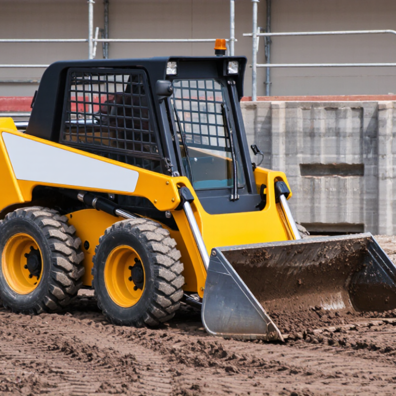
A skid steer is a compact loader with four wheels and a rigid frame. It turns by changing the speed or direction of each side’s wheels. The left wheels can move forward while the right wheels slow down or reverse. This creates a tight turning radius, sometimes with a slight ground scrape.

It has a front-mounted lift arm and a quick-attach plate for different tools. A bucket handles soil, gravel, and construction debris. A pallet fork moves supplies, while an auger drills into prepared ground. Hydraulic pumps send pressurized fluid through valves and cylinders. These cylinders raise the arm, tilt the attachment, and control working force. The operator manages these functions with hand controls and foot pedals, depending on the machine design.

The cab is small but practical. Its protective frame, adjustable seat, visibility, and warning systems support safer operation. Daily checks should include hydraulic hoses, tire condition, fluid levels, and attachment locks. Small leaks matter. A loose connection can reduce lifting power or create a serious hazard. Skid steers are powerful, but they are not suitable for every surface. Wet clay can reduce traction, and uneven loads can affect stability. I find their compact size useful in crowded work areas, yet this advantage can encourage rushed movements. Smooth controls and a steady load remain more important than speed.

How the Skid-Steer Drive System Works

A skid steer moves through a simple but powerful drive concept: independent control of the left and right wheel groups. The engine powers hydraulic pumps, which send pressurized fluid to hydraulic motors. Each motor turns a chain, axle, or wheel assembly. The operator controls these systems with hand levers or joysticks.

Push both controls forward, and the machine travels straight. Pull them back, and it reverses. Push one control farther than the other, and the machine follows a curved path. For a tight turn, one side slows while the other keeps moving. The skid steer can even rotate within its own footprint. The tires or tracks slide slightly across the ground during this maneuver.

That sliding action creates excellent turning ability, but it also demands careful operation. Loose gravel may gather beside the tires. Wet soil can increase resistance and reduce control. An experienced operator watches the surface, not only the control handles. Smooth inputs usually protect the hydraulic system and improve accuracy.

The system is efficient, yet it is not effortless. Uneven tire pressure, worn chains, or contaminated hydraulic fluid can make steering feel uneven. This point is easy to overlook. Regular inspections help identify heat, leaks, unusual noise, and delayed movement before they become serious problems. In daily work, gentle control often matters as much as engine power.

Key Components and Their Functions

A skid steer is a compact loader built around a powerful hydraulic system. Its engine supplies energy to hydraulic pumps, which send pressurized fluid through control valves. These valves direct flow to hydraulic motors and cylinders. The motors drive the wheels or tracks, while the cylinders raise the lift arms and tilt the attachment.

The operator controls movement through joysticks or hand controls inside the cab. A quick-attach coupler connects buckets, forks, augers, and other tools. The frame carries the load, while the counterweight helps maintain balance during lifting. A cooling system protects the engine and hydraulics from excessive heat. Protective cab structures also reduce injury risks during rollover or falling-object incidents. No component works alone. A weak hydraulic filter, for example, can reduce performance across the entire machine.

Tips: Check hydraulic hoses for cracks, leaks, and bulges before operation. Inspect the attachment pins and coupler connection every time. Keep the cooling screen clean, especially in dusty conditions. Use smooth control movements; aggressive inputs can strain cylinders and tires. The most overlooked detail is often the fluid level. Still, fluid checks alone are not enough. Listen for unusual pump noise and watch for slow arm movement. These signs may suggest contamination, wear, or trapped air. Always follow the equipment manual and site safety rules. Shortcuts can become expensive.

What Is a Skid Steer and How Does It Work? — Key Components and Their Functions

Component or System Typical Characteristics Primary Function How It Works
Diesel Engine Commonly about 35–100 horsepower, depending on machine size Provides the mechanical power required for driving the machine and operating hydraulic equipment. The engine converts fuel energy into rotational power, which is transferred to hydraulic pumps and auxiliary systems.
Hydraulic Pumps Usually includes hydrostatic drive pumps and implement hydraulic pumps Creates pressurized hydraulic flow for propulsion, lifting, tilting, and attachment operation. The pumps draw hydraulic fluid from the reservoir and send it through valves and motors at controlled pressure and flow rates.
Hydrostatic Drive System Two independently controlled hydraulic drive circuits Moves the machine forward, backward, and at variable speeds while enabling skid steering. Hydraulic motors drive the wheels or tracks on each side. Different speeds or directions on the two sides produce turning.
Wheels or Rubber Tracks Wheeled machines suit firm surfaces; tracked machines provide greater flotation and traction Transfers drive power to the ground and supports the operating weight. The drive system rotates the wheels or track sprockets. Track versions spread machine weight over a larger contact area.
Lift Arms Typically configured with radial-lift or vertical-lift geometry Raises and lowers the attachment and positions the load at different working heights. Hydraulic lift cylinders extend or retract to move the arms through their designed lifting path.
Lift Cylinders Double-acting hydraulic cylinders Supplies the force needed to raise, hold, and lower the lift arms. Pressurized fluid enters either side of the cylinder piston, creating controlled linear movement.
Tilt Cylinders Hydraulic cylinders connected between the lift arms and attachment carrier Tilts the bucket or other attachment for digging, carrying, dumping, and leveling. The operator adjusts hydraulic flow to extend or retract the cylinders and change the attachment angle.
Quick- attach Coupler Mechanical or hydraulic attachment connection system Allows operators to connect and remove buckets, forks, augers, breakers, and other tools. The coupler engages the attachment mounting points and is secured with locking pins or hydraulic mechanisms.
Auxiliary Hydraulics Standard-flow systems often provide approximately 15–30 gallons per minute; high-flow systems provide more Powers hydraulic attachments such as brush cutters, trenchers, sweepers, and breakers. The operator activates auxiliary valves to direct hydraulic fluid through supply and return lines to the attachment.
Operator Controls Joystick or hand-and-foot control layouts are common Controls travel direction, steering, lift-arm movement, attachment tilt, and auxiliary functions. Electrical or hydraulic control signals adjust valves and pump output in response to operator input.
Hydraulic Reservoir and Filtration Reservoir, filters, cooling components, hoses, and valves form a closed working circuit Stores, cleans, cools, and distributes hydraulic fluid. Fluid returns from hydraulic components to the reservoir, passes through filters and cooling equipment, and is recirculated.
Cooling System Radiator, hydraulic-oil cooler, fan, and related airflow passages Maintains suitable operating temperatures for the engine and hydraulic system. Airflow removes heat from engine coolant and hydraulic oil before the fluids return to their respective circuits.
Counterweight and Chassis Compact rigid frame with rear counterweight and low center of gravity Supports major systems, protects internal components, and improves balance during lifting. The frame distributes loads while the counterweight helps offset the attachment and payload carried at the front.
Protective Operator Cab Overhead guard or enclosed cab with rollover and falling-object protection features Protects the operator from rollover hazards, falling materials, weather, and workplace debris. The protective structure forms a reinforced safety zone around the operator and may include doors, windows, and climate control.
Bucket or Work Attachment Attachment type varies according to digging, loading, grading, lifting, or material-handling tasks Performs the specific task for which the skid steer is being used. The attachment receives mechanical support from the coupler and may receive hydraulic power through auxiliary lines.
Skid-Steering Mechanism Zero-radius or very tight turning capability Enables maneuvering in confined areas without a conventional steering axle. The operator slows, stops, or reverses one side while driving the opposite side, causing the tires or tracks to skid during the turn.

Note: Specifications vary by machine size, lift configuration, attachment, operating weight, and hydraulic package. Always consult the applicable operator’s manual for exact ratings and safety requirements.

How Sany Skid Steers Operate in Different Tasks

A skid steer is a compact loader built for tight work areas. Its left and right wheels operate independently, allowing the machine to turn within its own length. The operator uses two hand controls to adjust travel speed and direction. This design feels responsive, but it demands careful movements on uneven ground.

During loading, the lift arms raise buckets filled with soil, gravel, or construction debris. The operator keeps the load low while traveling, then raises it beside a truck or material pile. For grading, a blade attachment needs steady speed and small control changes. Hydraulic flow powers each attachment, including augers, sweepers, trenchers, and forks. Different tasks require different attachment settings.

On landscaping jobs, narrow tires or tracks reduce surface damage and improve traction. Tracks usually perform better on soft soil, while tires move faster across firm yards. In snow removal, a blower or plow must match the site’s width and surface conditions. Confined spaces expose the machine’s main strength. It can rotate around fences, walls, and stored materials with limited repositioning.

I have found that operator judgment matters as much as engine power. A full bucket can block visibility. That is a real hazard. Mirrors, cameras, and controlled reversing help, but they do not replace direct checks. Operators sometimes push too aggressively, causing wheel slip or rough grading. Slower inputs often produce cleaner results, although experienced workers can still misjudge changing ground conditions.

Safety, Maintenance, and Operating Considerations

A skid steer is a compact loader with a rigid frame and lift arms. It turns by changing the speed of each side’s wheels or tracks. Hydraulic pumps transfer engine power to the drive system and attached tools. Buckets, augers, and sweepers connect through a quick-coupler. The operator controls movement, lifting, and attachment flow from the cab.

Safety begins before the engine starts. Inspect tires or tracks, hydraulic hoses, pins, guards, and the attachment connection. Look for leaks under the machine. Keep bystanders outside the working zone, especially during reversing. The operator should wear the seat belt and keep the restraint bar lowered. Never carry people in the bucket. Uneven ground can shift the load quickly, so travel with the attachment low and loaded material close to the machine.

Daily maintenance includes checking engine oil, coolant, hydraulic fluid, and grease points. Clean the radiator screen when dust builds up. A blocked screen can cause overheating.

Follow the service schedule, but do not treat it as perfect. Harsh soil, long shifts, and heavy attachments may require earlier inspections. Stop work when controls feel slow, steering becomes uneven, or a warning light appears.

Tips: Use gentle joystick movements near walls and trenches. Test the attachment at low speed. Park with the arms lowered, controls neutral, and the brake applied. Keep a simple inspection log. Small notes often reveal repeated problems.